 Most recent progress...as of 1/28/2001
Assembling the Grizzly 9x20 lathe
Radius Cutting Attachment for Sherline Lathe
Utility Compound Slide
The Anglette Project
Mini Mill Down Feed & 44
Tooth Downfeed Project
Grizzly
9x20 setup.
April 26,
2004:
I discovered some time ago that the "feet" of the lathe were not
machined
flat with respect to the bed ways, or any other part of the lathe for
that
matter. So, in my original attempt to correct the situation, I
think
I made it worse. Now, I'm in the process of trying to file and
scrape
the bottom of the feet to be parallel to the underside of the
ways.
The bottom of the feet really aren't critical surfaces, but I wanted to
practice scraping to see how good I could do. If I screw it up, I
can always use shims to get the bed level.
[Note: take
picture of setup and put it here]
Most recent progress...as of 1/28/2001
Radius cutting attachment for the Sherline Lathe. However, first I must figure out why the little Sherline milling vise fixed jaw is NOT square! Answer: Because it was machined that way! (Or perhaps it was the anodizing that did it). Now, how to correct?
January 28, 2001 update: Well, I just couldn't help myself. I decided to "fix" the Sherline milling vise. I manage to true up the fixed jaw, but now I find that the metal jaw liner is not of uniform thickness. Another project. I wish I had a surface grinder.
Also, I found that the column just isn't square with the base. I am investigating where the sources for error are. I know that the preferred corrective action is to shim the column, but first, I want to find out if there are any burrs, bump, bulges, or whatever.
February 2, 2001 update: The column itself seems to be square with the base. The base of the milling machine itself seems to be the culprit. It isn't flat where the column is mounted. Now, how to fix? Do I shim it? Do I try to machine it by attaching a temporary milling or grinding spindle to the x/y table?
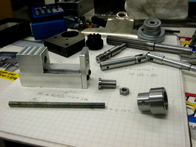
February 11, 2001 update: I decided to mill the base. I tried rigging up a temporary milling attachment using a Dremel, but I was unhappy with the depth control. The following picture is my solution. I figure that a small 3" compound would be useful in many applications.
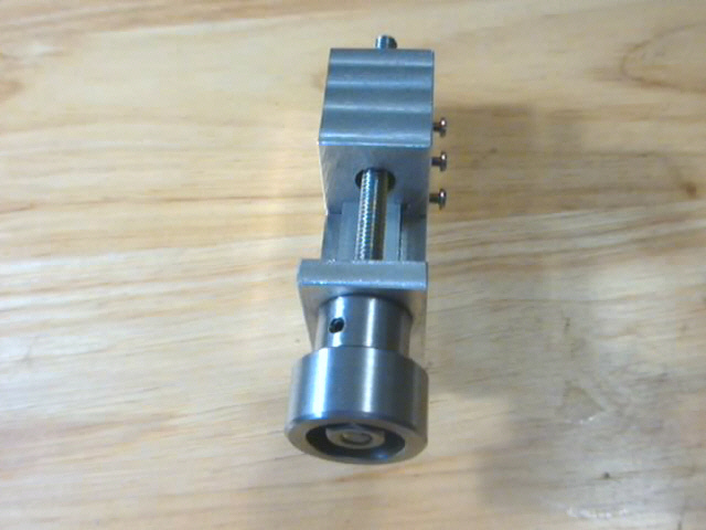
Here is a picture parts of the of the knob assembly. The parts in the background are from the micrometer downfeed of my Mini Mill.
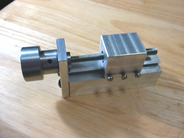
Now for a bit of explanation. I wanted to use a piece of standard 1/4-20 threaded rod for the lead screw. I looked at the way they connect the threaded rod to the hand wheel on the Sherline milling machine (and all of their other machines) and I thought that I could make an improvement. The one problem with the Sherline method is that you don't have an easy way to take up the slack for backlash. On the left, you see the piece of threaded rod. In the center, behind, you see a small 3/8" cylinder with a 1/2" flange on the left end. It drilled and tapped for 1/4-20. Next is a standard hex nut, and on the right, the knob. The knob is threaded in the right end. The rod is threaded into the knob, and fixed in place with the 1/4-20 hex jam nut. There is a recess on the right side of the knob as shown for the nut. The cylinder slides through the 1/4" plate on the end of the compound, as shown in the pictures of the device assembled. The threaded rod is screwed into the cylinder until the left side of the knob is up against the 1/4" plate. A set screw through the side of the reduced portion of the knob locks the cylinder in place with respect to the knob. Adjustment is by simply loosening the set screw and turning the cylinder on the threaded shaft.
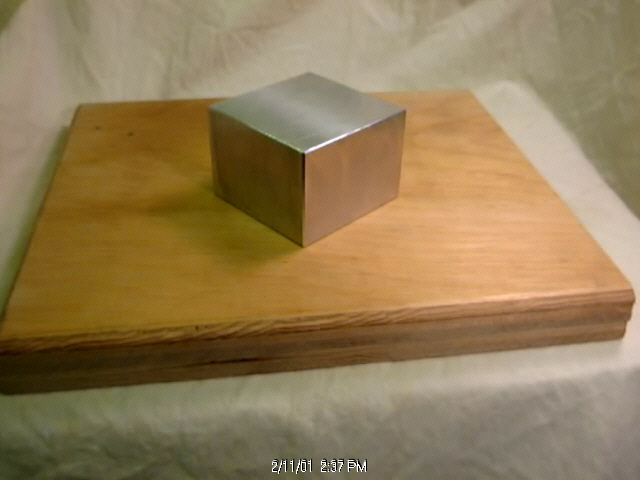
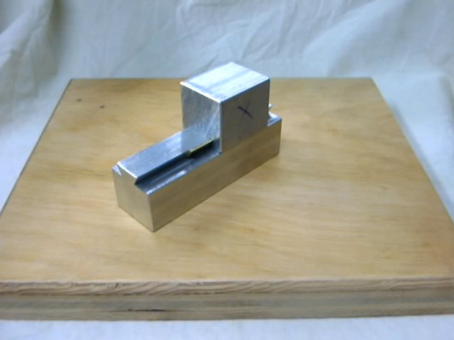
After doing all of this, I decided on a much simpler method. I took a length of 1x1" aluminum rod and attached the hand piece of a Dremel Flex Shaft tool to the end of it as shown. I clamped the holder to the table.
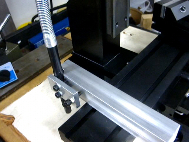
After a lot of fussing with shims beneath the holder, I was able to position a small carbide end mill (the kind used for making electronic circuit boards) about 0.002" inches below the surface of the table. Starting from the back end, I milled a rectangular area where the column now sits. This way, I was able to produce a surface that is parallel to the motion of the table. It seems to have worked.
While making this, I needed to make the small brass gib. That required milling the edges of the gib at a 30 degree angle. I finally accomplished this by gripping one of those small "machinist's insert vises" in my regular machine vise, tilted to the proper angle. I think that it would be good to have a small sine vise made like one of these insert vises for working on small stuff. They are only about 1" wide, and can open about only 3/4". I think I'll call it "The Anglette Project". That's next time in Uncle Bill's Basement.
I am in the midst of creating a 44 tooth worm drive for the downfeed.
w.j.ward
June 10, 2001 (When can I book my trip to Jupiter?)
Update: April 26, 2004